Nitek FRS3xx000R00 Manuel d'utilisateur
Naviguer en ligne ou télécharger Manuel d'utilisateur pour Matériel Nitek FRS3xx000R00. Nitek FRS3xx000R00 User Manual Manuel d'utilisatio
- Page / 2
- Table des matières
- MARQUE LIVRES
Résumé du contenu
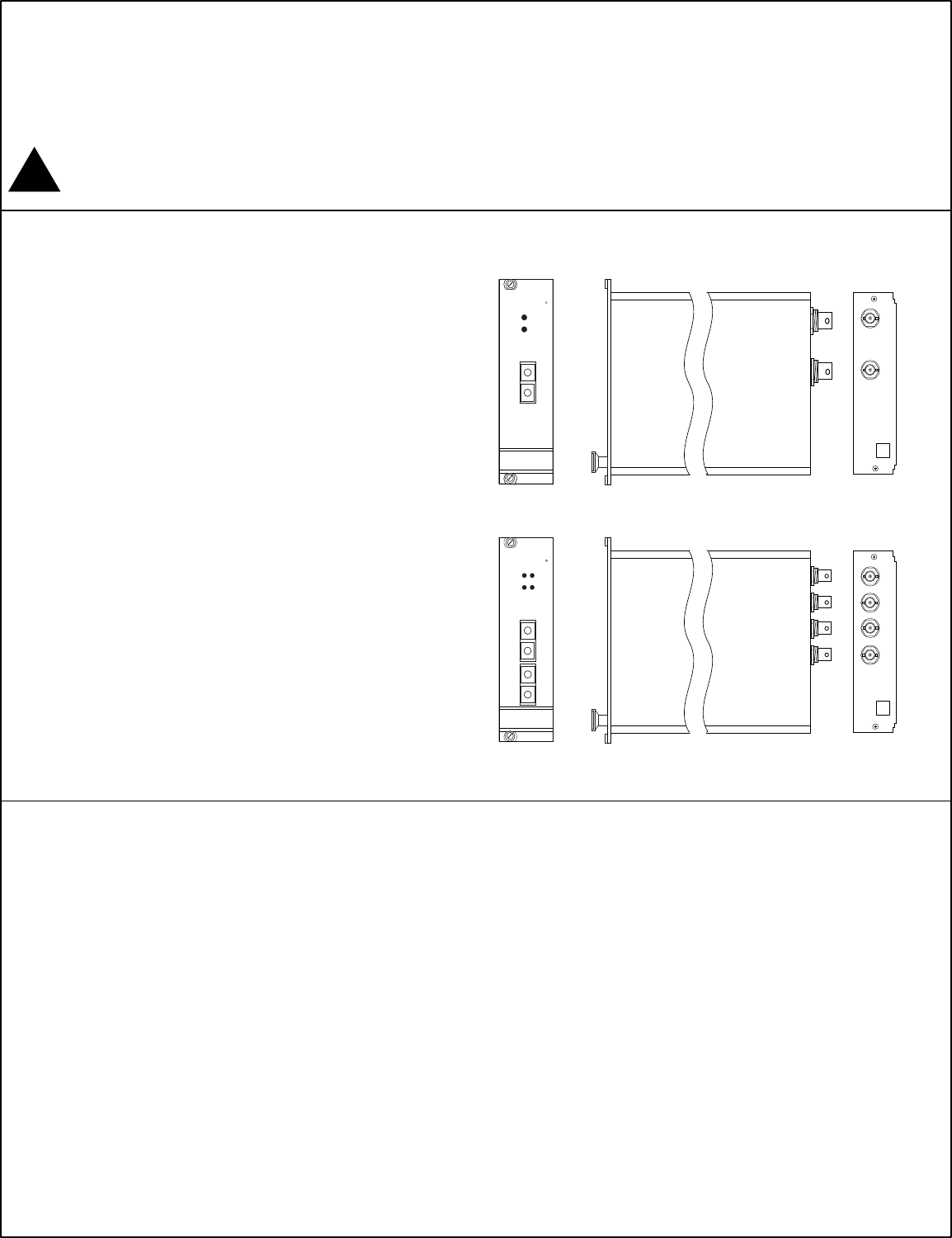
Installation Manual FRS3xx000R00 Rack Card 1, 2 and 4 Camera Rack Card Note: This installation should be made by a qualified service person and confor
Video In (1 or more) Transmitter Back Panel Typical Installation Diagram POWERVIDEO / OPTOOPTO IN / OUTCH1CH2CH3CH4NITEKRCH1CH2CH3CH4CH1CH2CH3 CH4Tr
Produits connexes et manuels pour Matériel Nitek FRS3xx000R00
 (30 pages)
© 2020, manymanuals.fr. Tous droits réservés | 1.044 s |
 Manymanuals.com
 Manymanuals.de
 Manymanuals.fr
 Manymanuals.it
 Manymanuals.pl
 Manymanuals.cz
 Manymanuals.es
 Manymanuals-pt.com
Commentaires sur ces manuels