Nitek FTS324104R00 Manuel d'utilisateur
Naviguer en ligne ou télécharger Manuel d'utilisateur pour Matériel Nitek FTS324104R00. Nitek FTS324104R00 User Manual Manuel d'utilisatio
- Page / 2
- Table des matières
- MARQUE LIVRES
- NITEK ® 1
- OPTO IN / OUT 2
Résumé du contenu
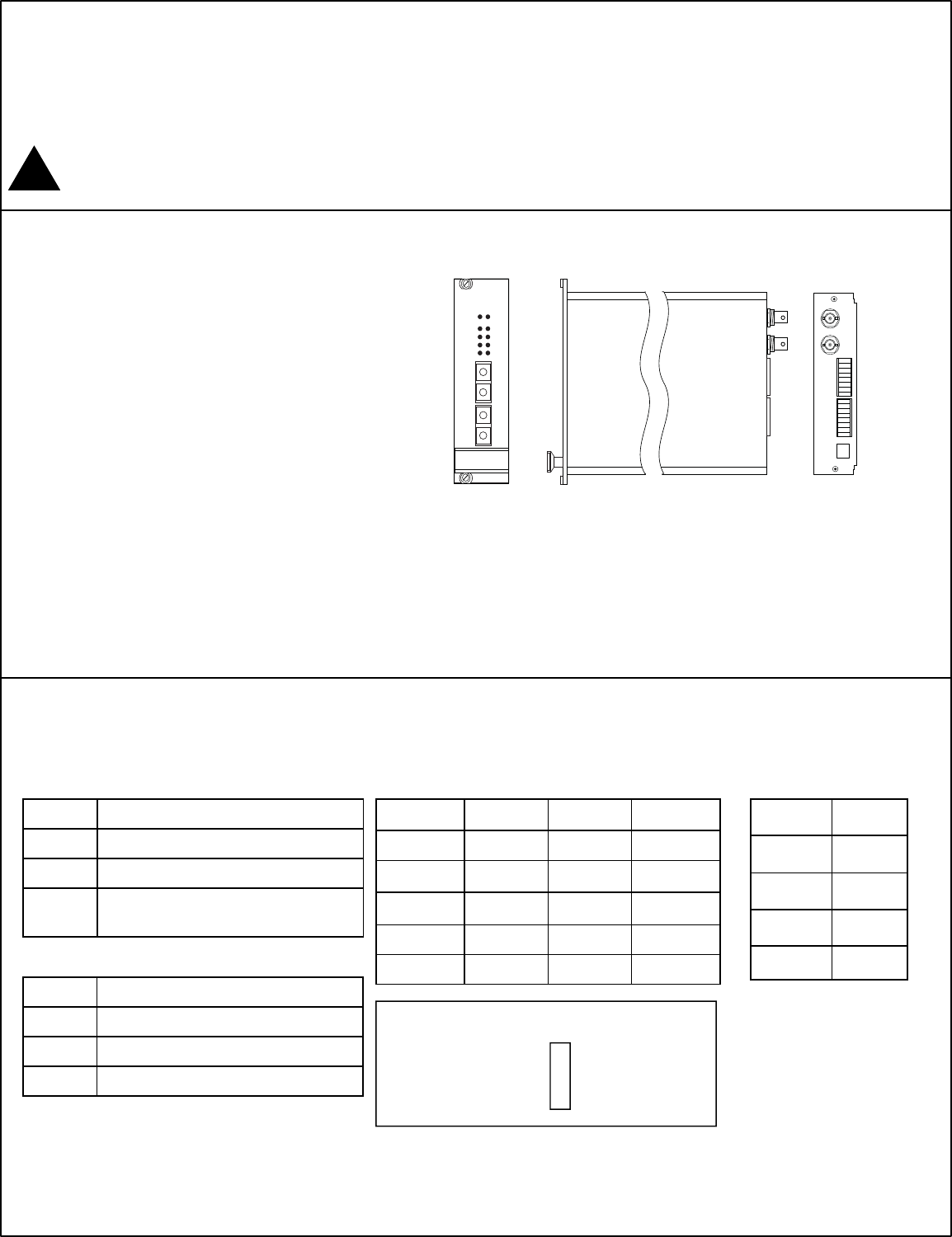
Installation Manual FTS324104R00 Dual Transmitter 2 Camera Transmitter w/Data and Aux Comm. Note: This installation should be made by a qualified serv
Typical Installation - FTS324104R00 NITEKCH1POWERVIDEO/OPTOCH2DATA OUTDATA INALARM OUTALARM INCH1CH2OPTO IN / OUT CH 1CH2BACK FRONT Connect incoming
Produits connexes et manuels pour Matériel Nitek FTS324104R00
 (30 pages)
© 2020, manymanuals.fr. Tous droits réservés | 0.914 s |
 Manymanuals.com
 Manymanuals.de
 Manymanuals.fr
 Manymanuals.it
 Manymanuals.pl
 Manymanuals.cz
 Manymanuals.es
 Manymanuals-pt.com
Commentaires sur ces manuels